
Ring Main Unit (RMU) vs. Transformer: Core Functional Differences, Application Scenarios and Engineering Design Guidelines in Medium-Voltage Distribution Systems
For junior electrical engineers, power system designers, site construction technicians, and project managers who are new to the medium-voltage (MV) distribution industry, there exists an extremely common and easily overlooked technical misunderstanding. In daily substation design, compact kiosk station layout, and power distribution system commissioning, many practitioners tend to generalize all metal-enclosed power equipment inside MV substations as “substation power devices” and equate the functions of Ring Main Units (RMUs) and distribution transformers. A prevalent misconception in the industry goes as follows: “Both ring main units and transformers are standard electrical equipment installed in substations, so their core functions and system roles are essentially the same.”
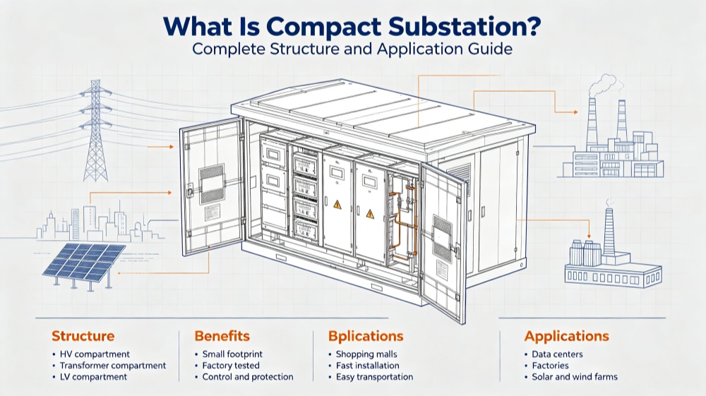
Through long-term technical communication, project collaboration and design review work with EPC engineering teams, municipal facility engineers, grid operation units and third-party power engineering partners, we have fully recognized that this cognitive confusion is completely understandable and widespread in the industry. The fundamental reason for this misunderstanding lies in the structural layout characteristics of modern compact power distribution stations. In urban compact integrated substations, outdoor kiosk-type substations, and container-type prefabricated substations that are widely used in commercial complex projects, residential community supporting power projects and industrial park power supply projects, ring main units and distribution transformers are always arranged in adjacent positions. In most standardized compact station designs, the two types of equipment are even integrated in the same closed metal cabinet or unified equipment cabin, with consistent external industrial appearance and similar overall installation dimensions.
However, superficial similarity in installation form and appearance cannot cover the essential differences in working principle, system positioning, core function, protection logic and operation and maintenance modes of the two devices. In actual engineering design and on-site operation, confusing the functional positioning of ring main units and transformers will lead to a series of serious hidden dangers in the whole life cycle of the power distribution system. In the early design stage, functional confusion will cause inaccurate equipment parameter specification selection, mismatched protection configuration schemes and missing safety protection links. In the construction and commissioning stage, it will lead to unreasonable equipment layout, non-compliant cable connection logic and difficult on-site construction coordination. In the formal operation stage, these design defects will evolve into potential safety hazards such as unisolable faulty lines, unprotected downstream loads, incomplete safety locking conditions and difficult fault troubleshooting, resulting in frequent power supply failures, increased equipment failure rates and even personal electric shock safety accidents in severe cases.
More importantly, many power distribution design drawings that seem completely standardized and compliant in paper review often have major logical defects in actual on-site docking and operation due to the confusion of RMU and transformer functions. The single-line diagram may have complete equipment labels and standardized circuit connections, but it cannot adapt to actual fault isolation, emergency power restoration, daily switching operation and equipment maintenance scenarios, resulting in low operational efficiency and poor system reliability. In view of this common industry pain point, this article will systematically sort out the core differences between ring main units and transformers in combination with mainstream MV distribution system architectures at home and abroad.
We will adopt plain and easy-to-understand engineering expression, abandon obscure academic theoretical formulas, and focus on explaining the working logic, system positioning and application scenarios of the two devices in the MV to low-voltage (LV) power supply chain. At the same time, combined with the internal drawing review standards and on-site engineering experience accumulated in long-term project practice, we will summarize practical screening questions and design verification key points for equipment selection and scheme optimization. The core original intention of this article is not to carry out equipment marketing and product promotion, but to provide systematic technical popularization and design guidance for front-line engineering practitioners, help every designer and operator clarify the essential differences between the two core power distribution equipment in the early design stage, avoid repeated modification of drawings and equipment replacement caused by cognitive errors, greatly save project time cost and economic cost, and effectively reduce operation risks and maintenance costs in the later stage of the power distribution system, so as to build a more stable, safe, efficient and easy-to-maintain medium and low voltage power distribution system.
1. Basic Definition and Essential Working Principle of Core Equipment
To completely eliminate the cognitive confusion between ring main units and transformers, we must start from the most essential equipment definitions and working principles, clarify the core positioning of the two in the power system, and lay a solid theoretical foundation for subsequent design, selection, operation and maintenance work.
1.1 What is a Ring Main Unit (RMU)?
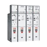
A Ring Main Unit (RMU) is a professional medium-voltage switchgear specially designed for MV distribution network operation, fault isolation and power supply protection. It is the core control and protection node of the ring network power supply system, and is widely applicable to ring-shaped, looped and radial MV power distribution networks of 6kV to 36kV voltage level. Different from conventional isolated switchgear, the ring main unit integrates multiple functional modules such as line incoming, line outgoing, sectional switching, fault isolation and grounding protection, and is a comprehensive modular switchgear integrating control, protection and safety isolation.
The core design concept of the ring main unit is to solve the safety operation and continuous power supply problems of the MV distribution network. In the traditional radial power supply network, once a line fails or equipment needs maintenance, the whole downstream area will be cut off, resulting in a large range of power outages. The emergence of ring main units perfectly makes up for the defects of the radial power supply mode. By building a closed-loop power supply topology, the RMU realizes bidirectional power supply of the line, and provides safe and operable technical means for on-site operators to carry out daily power distribution adjustment, fault emergency disposal and equipment maintenance.
In actual engineering operation scenarios, the core functional values of ring main units are reflected in four key dimensions. First, it realizes safe load switching, and operators can complete line power transmission and switching of power supply branches through standardized switching operations without cutting off the whole network power supply. Second, it supports accurate fault section positioning and isolation. When a short circuit, grounding or overload fault occurs in a certain section of the MV line, the RMU can quickly lock the faulty section through the matching protection device and isolate the faulty line segment in time to prevent the fault from spreading to the whole network. Third, it guarantees uninterrupted power supply of the system. After isolating the faulty section, the ring network system can realize power supply reversal through the opposite loop of the ring network, maintain normal power supply of non-faulty lines and downstream loads, and greatly improve the power supply reliability of the distribution network. Fourth, it provides reliable safety protection for downstream equipment and lines. According to different feeder types and load levels, the RMU is equipped with fuse protection or circuit breaker protection modules to cut off faulty current in time and avoid equipment burnout and line damage caused by overload and short circuit faults.
We can use a vivid and industry-recognized metaphor to define the positioning of the ring main unit in the power system: the ring main unit is thetraffic controller of medium-voltage power flow in the distribution network. It is responsible for commanding the transmission direction of power, isolating faulty road sections, dredging normal power supply lines, and ensuring the orderly, safe and continuous operation of the whole MV power supply network.
1.2 What is a Distribution Transformer?
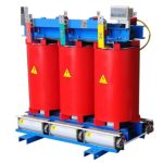
A distribution transformer is a static electromagnetic induction electrical equipment, which relies on the electromagnetic induction principle of alternating current to realize voltage level conversion and electric energy transmission. It belongs to power conversion equipment in the power system, not power control and protection equipment. Different from switchgear represented by RMU, the transformer has no line switching, fault isolation and network control functions, and its core value is to complete voltage matching between the upper-level power supply network and the lower-level load equipment.
In the urban and industrial medium and low voltage distribution system, the mainstream power supply mode is that the power grid transmits electric energy through 11kV or 24kV medium-voltage lines, while the terminal electrical equipment of buildings, factories and residential communities can only work normally under 400V low-voltage power supply. The voltage level difference between the upper grid and the terminal load needs to be converted by distribution transformers. The transformer steps down the 11kV/24kV medium-voltage electric energy transmitted by the grid to 400V low-voltage electric energy that meets the terminal load demand, providing qualified voltage and stable power capacity for all low-voltage electrical equipment.
It is crucial to clarify that the transformer cannot replace any function of MV switchgear. It has no switching components, cannot control the on-off of line power flow, cannot isolate faulty lines, and cannot provide safety protection for the power network. The whole operation process of the transformer is passive power conversion. As long as the upper-level RMU supplies power normally, the transformer will continuously perform voltage conversion work. Its core performance indicators are voltage conversion accuracy, load capacity (kVA rating), operating loss, insulation performance and cooling efficiency.
Similarly, we can define the transformer’s system positioning with a vivid metaphor: the transformer is the voltage converter and capacity provider between medium-voltage network and low-voltage load terminals. It is only responsible for converting high-level voltage into usable low-level voltage and providing sufficient power capacity for terminal loads, without participating in any network scheduling and fault control work.
2. Equipment Combination Logic and Operation Flow of Typical MV Distribution System
To thoroughly understand the matching relationship and functional differences between RMU and transformer, we need to sort out the complete power supply chain of typical commercial, residential and industrial power distribution projects, and clarify the sequential logic and division of responsibilities of each core equipment in the whole power supply process.
At present, the standardized power supply architecture of mainstream urban distribution network projects in the industry is unified and clear. The complete power transmission link from grid power access to terminal load power consumption includes four core equipment links in sequence: municipal power company MV incoming line, ring main unit, distribution transformer, and LV distribution panel. Each link is independent in function and closely connected in logic, forming a closed and safe power supply system.
The first link is the medium-voltage incoming line from the power supply bureau. Most urban formal power supply projects adopt ring-network bidirectional feeder power supply mode. Different from the single radial power supply of rural power grids, the ring-network incoming line has two power supply channels, which can realize mutual standby of power sources, and fundamentally improve the stability and anti-interference ability of the power supply system, which is the core foundation of high-reliability power supply in urban areas.
The second link is the ring main unit, which is the core control node of the whole MV power supply link. All MV incoming lines and transformer feeders need to be connected through the RMU. It undertakes three core tasks in the system: switching control of transformer feeders, safety isolation of faulty lines and full-cycle protection of downstream power supply branches. All line switching, fault disposal and maintenance safety isolation operations in the MV ring network are completed based on the RMU.
The third link is the distribution transformer, which is the only voltage conversion node in the medium and low voltage power supply chain. It is located at the downstream of the RMU, receives the medium-voltage electric energy after switching and protection by the RMU, and converts it into standard low-voltage electric energy to provide power source for the subsequent low-voltage distribution system.
The fourth link is the low-voltage distribution panel. It receives the low-voltage electric energy converted by the transformer, and distributes the electric energy to each floor, each functional area and each terminal equipment of the building through multiple outgoing breakers, finally realizing the power demand of terminal loads.
In the whole ring network power supply system, the ring main unit plays a decisive core role in maintaining the safe and stable operation of the system. When a line fault occurs or the equipment needs power-off maintenance, the RMU can isolate the faulty section or the maintenance section without affecting the normal power supply of other branches of the ring network. It maintains the overall energized state of the ring network, realizes non-stop maintenance and fault rapid recovery, and is the key equipment to ensure the continuity of urban power supply.
3. Comprehensive Comparative Analysis of RMU and Transformer
In order to help engineering practitioners quickly and accurately distinguish the two types of equipment in design, construction and drawing review, we have sorted out a multi-dimensional detailed comparison table based on years of on-site engineering experience and internal design review standards, covering core functions, voltage levels, problem solving directions, internal components, operation modes, protection responsibilities, installation positions and post-removal impact, realizing full-dimensional differential identification.
Comparison Item | Ring Main Unit (RMU) | Transformer |
Core Main Function | Realizes switching, sectional isolation and safety protection of medium-voltage distribution network lines, controls power flow direction and network operation state, and supports ring network power supply and fault emergency disposal | Relies on electromagnetic induction principle to complete medium-voltage and low-voltage voltage level conversion, provides matched working voltage and stable power capacity for terminal low-voltage loads, and does not participate in network control |
Typical Voltage Level | Only applicable to medium-voltage systems, the mainstream applicable voltage range is 6kV to 36kV, and the specific insulation level and rated voltage are matched according to the local grid system standards | Dual voltage matching, the primary side is connected to medium-voltage (6-36kV) lines, and the secondary side outputs standard low-voltage (400V), supporting step-up and step-down conversion in special scenarios |
Core Problem Solved | Solves the problems of difficult line isolation, uncontrollable power flow, unprotected faults and discontinuous power supply in medium-voltage distribution network operation, and realizes refined network safety control | Solves the problem of voltage level mismatch between grid medium-voltage power supply and terminal low-voltage load demand, converts unusable high voltage into usable load voltage, and provides sufficient power bearing capacity |
Main Internal Components | Core functional components include load break switches, earthing switches, fuse combination switches or vacuum circuit breakers, copper busbars, mechanical interlock devices, fault indication sensors and operating mechanisms | Core structural components include silicon steel iron core, high and low voltage winding coils, insulating medium, cooling system (air cooling/oil cooling), sealing structure, temperature sensor and oil pressure protection device |
Operation Mode | Frequent manual and automatic switching operations are required in daily operation, including load switching, fault isolation, line grounding and safety locking, with flexible operation logic and frequent state changes | Long-term continuous static operation, no frequent manual operation under normal working conditions. After power-on, it runs stably for a long time, and only stops operation during maintenance and fault overhaul |
System Protection Role | Active protection equipment, which provides full-range feeder protection for ring network lines and transformer branches. It can cut off fault current in time through fuses or circuit breaker relays to protect downstream equipment and lines | Passive protected equipment, which does not have active network protection capability. It mainly relies on the upstream RMU for fault protection, and is only equipped with internal auxiliary protection such as temperature monitoring and gas overpressure protection |
Installation Location | Installed in medium-voltage switch room, outdoor compact kiosk station, prefabricated substation and ring network cabinet centralized area, belonging to medium-voltage core control equipment | Installed adjacent to the RMU in the substation, located in the downstream power conversion link, can be integrated in the same equipment cabin with the RMU, and matched with low-voltage distribution panel |
Impact of Equipment Removal | The medium-voltage network loses all switching and isolation capabilities, faults cannot be isolated, line maintenance cannot be safely carried out, the whole network loses protection conditions, and the system is in a high-risk unsafe operating state | The medium-voltage power cannot be converted into usable low-voltage power, all terminal low-voltage loads lose power supply, the whole downstream power distribution system is paralyzed, and the load capacity of the power system is completely lost |
4. Root Cause Analysis of Industry Cognitive Confusion
After sorting out the functional differences and system positioning of the two devices, we can clearly find that the working principles and core functions of RMU and transformer are completely different. However, why do most new engineers and even individual experienced designers still confuse the two devices in actual work? We summarize the root causes of industry confusion based on project practice and technical training experience.
The first and most intuitive reason is the similarity of external appearance and installation form. With the continuous upgrading of urban power distribution equipment, traditional large-scale open substations have been gradually replaced by compact integrated kiosk substations and prefabricated container substations. In order to adapt to urban compact construction requirements, save land resources and beautify the urban power supply infrastructure image, modern power distribution equipment adopts standardized metal closed cabinet design. Both RMU and transformer are packaged in metal shell structures, with unified industrial appearance, similar installation volume and consistent on-site installation environment. For practitioners who have not in-depth understanding of internal structure, it is easy to equate the two as the same type of substation equipment.
The second core reason is the high correlation of installation positions. In all compact substation design schemes, the RMU and the transformer are designed in a fixed upstream and downstream matching mode. The RMU is responsible for medium-voltage incoming line control and protection, and the transformer is responsible for subsequent voltage conversion. The two are adjacent to each other and matched one-to-one in most projects, forming a fixed equipment combination mode. Long-term visual inertial cognition makes many people mistakenly believe that the two are supporting equipment with the same function.
The third deep-seated reason is the lack of systematic understanding of power supply chain logic. Most junior practitioners only pay attention to equipment installation and wiring construction, but do not sort out the whole logic of power transmission, control, protection and conversion of the distribution network. They cannot distinguish the essential difference between “network control and protection equipment” and “energy conversion equipment”, resulting in long-term cognitive confusion in equipment function.
It is necessary to emphasize again that the similarity of appearance and installation form is only the structural design optimization of modern power distribution equipment, which cannot change the essential difference between the two: the ring main unit is a switching control and safety protection device for power network operation, while the transformer is a power energy conversion device for voltage matching.
5. Core Differences in Protection Mechanisms (Most Practical Engineering Point)
In engineering design, on-site commissioning and operation and maintenance work, the difference between RMU protection and transformer protection is the most practical and most easily confused key technical point. The protection mechanism directly determines the equipment configuration scheme, parameter setting standard and fault disposal logic of the project, and is the core key to ensure the safe operation of the system.
5.1 Protection Logic and Scope of Ring Main Unit
The ring main unit is the active protection core of the medium-voltage distribution network, and all protection actions are actively triggered by the RMU equipment itself and its supporting protection components. Its protection scope covers the whole ring network feeder and all downstream transformer branches, which can be divided into two core protection scenarios.
The first is the protection of ring network trunk feeders. The RMU is equipped with load break switches and earthing switches corresponding to the ring network topology. When a single-phase grounding, phase-to-phase short circuit or line overload fault occurs in any section of the ring network trunk line, the RMU can quickly complete fault section judgment, isolation and power supply switching. It cuts off the faulty line section, retains the normal power supply of the non-faulty section, and realizes the sectionalized safe operation of the ring network.
The second is the protection of transformer special feeders. As the upstream protection equipment of the transformer, the RMU is equipped with professional protection modules for each transformer outgoing feeder. At present, there are two mainstream protection configuration schemes in the industry. The first is fuse-based protection scheme, which has the advantages of simple structure, low cost, stable performance and strong anti-interference ability, and is widely used in conventional small and medium-capacity distribution transformer projects. The second is circuit breaker + relay protection scheme, which has adjustable protection parameters, high action precision and strong selective coordination ability, and is the preferred scheme for large-capacity transformers, industrial complex power supply projects and projects with complex grid topology.
5.2 Protection Logic and Scope of Transformer
The transformer has no independent active network protection ability, and its safe operation completely depends on the protection of upstream RMU equipment. All faults occurring in the transformer body, such as winding short circuit, overload heating and insulation breakdown, need to rely on the timely breaking of the upstream RMU protection device to cut off the power supply and avoid fault expansion.
At the same time, the transformer is equipped with auxiliary internal monitoring and protection devices, which are used for body state monitoring and early warning, rather than network fault protection. For common oil-immersed transformers, the internal supporting protection devices include temperature sensors, oil level monitoring sensors, pressure relief valves and gas relays (Buchholz relays). These devices can monitor the operating temperature, oil level state and internal gas generation of the transformer in real time. When the transformer operates abnormally and generates heat, oil leakage or internal discharge gas, the monitoring device will send out alarm signals or linkage trip signals to remind operators to carry out maintenance and disposal.
To sum up, the core protection logic of the two is clear and unambiguous: The ring main unit protects the transformer and the whole medium-voltage network, and the transformer only undertakes self-state monitoring without network protection function. This is the core basis for all equipment protection configuration and parameter setting in engineering design.
6. Differences in Safety Operation and Isolation Responsibilities
Medium-voltage power distribution operation belongs to high-risk electric power operation, and standardized safety isolation and locking procedures are the key to avoid personal electric shock accidents and equipment safety accidents. In daily safety operation specification review and on-site operation guidance, we found that many operation errors are caused by confusing the isolation functions of RMU and transformer.
All safety isolation operations of medium-voltage lines must be completed based on the ring main unit. The standardized safe operation process of medium-voltage equipment in the industry takes the RMU switching operation as the core, including six key steps in sequence: opening the switch to cut off the line power supply, verifying the complete isolation state of the line, installing grounding wires for safety grounding, implementing lock-out and tag-out (LOTO) locking measures, conducting on-site voltage detection to confirm no residual voltage, and finally carrying out maintenance and commissioning operation on downstream equipment.
The transformer is a passive power conversion device without any switching and isolation functions. It is impossible to realize line isolation and power-off protection by “stopping the transformer”. In any maintenance scenario of transformer body and downstream low-voltage system, the staff must operate the upstream RMU switchgear to complete line isolation and power-off locking. Only after the RMU confirms power failure, isolation and grounding can the transformer and low-voltage equipment be safely maintained.
This safety operation rule is mandatory in all power industry specifications. Confusing the isolation functions of the two devices will directly lead to non-compliant safety operations, leaving serious electric shock and arc flash accident hidden dangers for on-site operators.
7. Schematic Symbol and Logical Presentation on Single-Line Diagrams
The single-line diagram is the core drawing guiding project design, construction, commissioning and acceptance. Mastering the schematic symbols and logical presentation rules of RMU and transformer on the drawing is an important standard to distinguish the two equipment correctly. We sort out the drawing representation rules and practical engineering significance of core equipment as follows.
Single-Line Diagram Element | Standard Schematic Symbol Meaning | Practical Engineering Significance |
Ring Main Unit (MV Switchgear) | Displayed as switch, fuse or circuit breaker module connected on the medium-voltage busbar, with clear feeder partition and switching state identification | It is the core control node of ring network feeders and transformer feeders, undertaking all medium-voltage line switching, isolation and protection functions, and is the key node to maintain ring network continuity |
Transformer | Displayed as two groups of winding symbols with voltage ratio labels, intuitively reflecting medium-low voltage conversion relation | Realizes step-down or step-up conversion between medium-voltage grid and low-voltage load, matches system voltage level, and provides load power capacity |
Low-Voltage Distribution Panel | Displayed as combined symbols of circuit breakers and multiple outgoing feeders | Distributes the converted low-voltage power to all terminal loads, realizing refined power distribution of low-voltage system |
In all ring network power supply project drawings, the RMU is always the key node connecting the whole ring network. It connects the incoming lines of the municipal power grid and the outgoing lines of each transformer branch, and realizes the closed-loop operation and safe isolation of the ring network. The transformer is only a single voltage conversion node at the downstream of the RMU, without any network connection and control function. By distinguishing the drawing symbols and logical positions, designers can effectively avoid functional design errors caused by equipment confusion.
8. Standard Selection Guidelines for Ring Main Units and Transformers
The most direct engineering value of distinguishing RMU and transformer functions is to standardize equipment selection logic, avoid parameter mismatch and equipment waste, and ensure that the selected equipment fully matches the actual operation demand of the system. The selection dimensions and core standards of the two equipment are completely independent and cannot be confused.
8.1 Core Selection Basis of Ring Main Unit
RMU selection must be fully based on the actual topology and operation demand of the medium-voltage distribution network, not limited by fixed voltage labels. The key selection dimensions include eight core modules.
First, network topology confirmation. It is necessary to clarify whether the project adopts ring network power supply or radial power supply, and confirm the number of incoming and outgoing feeders required by the system, so as to determine the basic configuration of the RMU. Second, cabinet configuration selection, including common 2-in-1-out, 3-in-1-out and multi-in multi-out configurations, matching the number of project power supply branches. Third, rated voltage and insulation level, which shall be strictly matched according to the local grid system voltage and environmental insulation requirements. Fourth, rated current and short-circuit withstand capacity, which need to meet the system fault level and ensure that the equipment can withstand short-term fault current impact. Fifth, protection mode selection, selecting fuse protection or circuit breaker relay protection according to the load importance and system complexity. Sixth, insulation technology selection, including gas insulation, solid insulation and other mainstream forms, matching the project environmental conditions and cost budget. Seventh, operational safety configuration, including mechanical interlock devices, earthing switch layout, cable detection channels and status indication devices, to ensure standardized safe operation. Eighth, environmental adaptability, selecting indoor or outdoor equipment according to the project site, and verifying the adaptability of equipment temperature resistance, humidity resistance, corrosion resistance and altitude adaptability.
8.2 Core Selection Basis of Transformer
Transformer selection focuses on load power demand and power conversion performance, which is completely different from RMU selection standards. The core selection indicators include rated capacity (kVA), impedance voltage parameter, cooling mode (oil cooling/air cooling), insulation grade, no-load loss and load loss performance. Designers need to select the transformer capacity according to the total load power of the terminal low-voltage system, and match the impedance parameters and loss indicators according to the system power quality requirements, so as to ensure stable voltage conversion and low-loss operation of the transformer.
9. Engineering Design Summary and Risk Prevention Suggestions
Through the systematic differentiation and in-depth analysis of ring main units and transformers, we can clearly conclude that although the two types of equipment are installed in the same substation and have similar external forms, they have essential differences in working principle, system positioning, core function, protection logic, safety operation and selection standards.
In the whole process of power distribution system design, drawing review, equipment procurement, construction commissioning and later operation and maintenance, engineering practitioners must completely eliminate the cognitive misunderstanding of “similar appearance means similar function”. In the design stage, it is necessary to clarify the respective functional boundaries of RMU and transformer, formulate targeted protection schemes and layout schemes, and avoid hidden dangers of equipment specification error and protection missing. In the construction stage, standardize equipment installation and wiring logic according to upstream and downstream functional relations. In the operation and maintenance stage, abide by safety operation specifications, take RMU as the core of line isolation and fault disposal, and avoid illegal operation behaviors.
Standardizing the functional cognition and design application of RMU and transformer is not only the basic requirement of engineering standardization, but also the key to improve the safety, stability and economy of the medium and low voltage distribution system. Accurate conceptual cognition in the early stage of the project can avoid a large number of design modifications, equipment replacement and on-site rectification work, effectively save project cost and construction period, and greatly reduce the operation failure rate and maintenance cost of the power system in the later stage, which is of great practical significance for the standardized construction and safe operation of urban distribution networks.
FAQ About RMU and Distribution Transformer
Q1: Can a ring‑main‑unit (RMU) replace a distribution transformer?
Definitely not. An RMU acts as medium‑voltage switchgear for switching, isolation and fault protection. A transformer executes voltage conversion by electromagnetic induction. They have separate working principles. RMU cannot step‑down 11kV or 24kV power to 400V low‑voltage supply for site loads.
Q2: Is it possible to isolate a faulty transformer just by powering off the transformer itself?
No. Transformers lack switch‑gear components for circuit disconnection. You must open and lock out the upstream RMU feeder to cut medium‑voltage power, then perform maintenance work on transformers and downstream low‑voltage panels.
Q3: Who provides primary protection for distribution transformers? RMU or internal transformer sensors?
The upstream RMU provides main protection for transformers via fuse switches or circuit‑breaker relay sets. Built‑in sensors such as temperature detectors and Buchholz relays only send out alarm signals instead of tripping faults actively.
Q4: Why do we install RMUs and transformers inside one compact kiosk‑type substation?
For urban construction planning. Integrating both devices within one shared metal cabinet saves land space and shortens MV cable runs. Even though they look alike externally, RMU handles incoming medium‑voltage power while transformers work on voltage reduction on the downstream side.
Q5: What will happen if I select the wrong RMU configuration for a ring‑network system?
Improper feeder setup (such as wrong 2‑in‑1‑out or 3‑in‑1‑out layout) will cause insufficient short‑circuit withstand capacity, failed fault isolation, loss of ring‑network continuity and even widespread unexpected power outages.
Q6: What factors decide RMU selection compared with transformer sizing criteria?
RMU selection depends on network topology, short‑circuit rating, insulation type (gas‑insulated or solid‑insulated), earthing design and local environment. Transformers are sized based on kVA load value, impedance, cooling mode and power‑loss indexes only.
Q7: Can radial power networks use ring‑main‑units?
Yes. RMUs are applied for both ring‑feed and radial‑feed systems. For radial networks, RMUs deliver basic isolation and over‑current protection even without bidirectional power‑supply functions.
Q8: Should I place transformer protection relays inside the transformer cabinet?
It is not recommended. Primary protection devices are installed inside the RMU feeder cabinet. Only auxiliary monitoring sensors stay inside transformer housings to avoid exposure of protection controls under humid outdoor conditions.
Q9: What symbols represent RMUs and transformers on single‑line diagrams?
RMU appears as switch‑fuse or circuit‑breaker modules on medium‑voltage busbars. Transformers are drawn as two sets of windings with marked voltage ratios to show MV‑LV step‑down conversion clearly.
Q10: Does a transformer need frequent manual operation similar to RMU?
No. RMUs require regular switching, grounding and isolation operations. Transformers run continuously with static working status and only shut down during maintenance or major faults.